Status register system
Status registers are used for monitoring the state of the device. In these registers operation statuses, errors, events, and questionable data results are stored.
There are 4 main registers:
| Abbreviation | Full name | used for |
|---|---|---|
| STB | Status Byte Register | Contains summary of all underlying registers. |
| ESR | Standard Event Status Register | Contains all errors and events that happened either while parsing a message or while executing. |
| QUES | Questionable Register | Represents all measurement parameters whose quality is not 100% accurate (e.g. because of an overload). |
| OPER | Operation Register | Represents all ongoing operations and the current state of the device. |
Additional to the registers an Error and Event Queue stores all the enabled errors and events alongside with their info message.
The interaction of these registers is shown in the following picture:
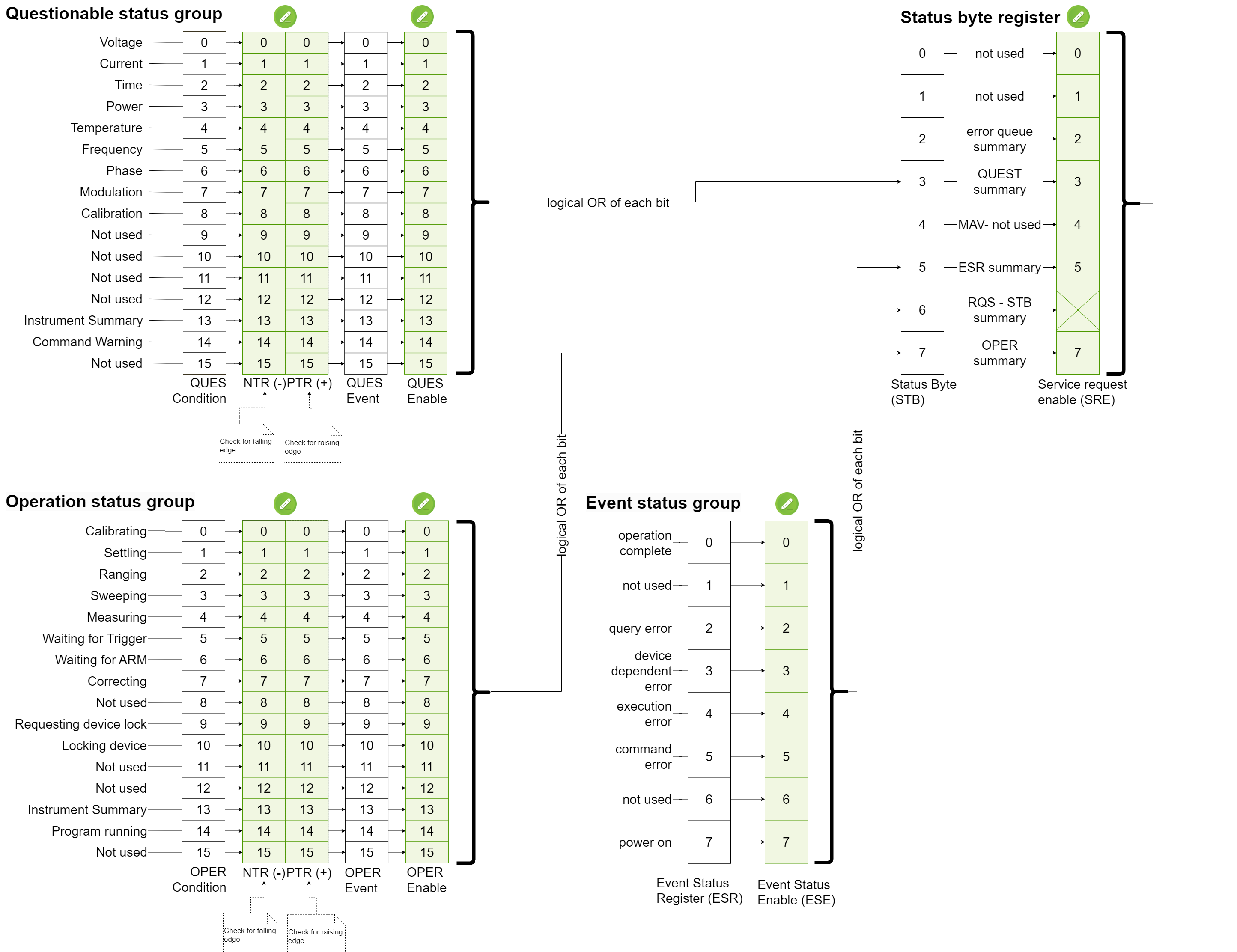
Status Byte Register (STB)
The status byte register acts as the main summary register that combines all the underlying status registers.
| Bit value | Code | Description |
|---|---|---|
| Bit 0 - 1 | Available to designer |
not used |
| Bit 1 - 2 | Available to designer |
not used |
| Bit 2 - 4 | Error/Event Queue |
indicates that the error event queue is NOT empty |
| Bit 3 - 8 | Questionable Status Summary |
indicates that some devices values are questionable and therefore the quality of the measurement is not guaranteed |
| Bit 4 - 16 | Message Available |
indicates that a message is available in the output queue. (Not used for the RAW Socket) |
| Bit 5 - 32 | Event Status Register Summary |
indicates that an event or an error occurred |
| Bit 6 - 64 | User Request |
Not used for the actual measurement device, because RAW socket does not support service requests. |
| Bit 7 - 128 | Operation Status Summary |
indicates that the device is currently performing some operations |
Standard Event Status Register (ESR)
The Standard Event Status Register contains all bits for possible error types as well as operation complete and power on events. It can be read with *ESR?. The reading of the register clears its content. This register cannot be set, but is rather a representation of the devices status and therefore it can only be read. Between the ESR and the status byte register there is a event status enable register (ESE). The ESE register can be read and written. It selects which bits of the ESR register should be forwarded to the 5th bit of the STB register. The 5th bit of the STB is calculated as a logical OR of the enabled bits of the ESR register.
E.g.:
- When the ESE register is 255 (all bits are enabled), the 5th bit of the STB is set if at least one of the bits in the ESR is set.
- When the ESE register is 0 (all bits are disabled), the 5th bit of the STB is never set.
- When the ESE register is 1 (only bit 1 -
operation completeis enabled), the 5th bit of the STB is only set if the bit 1 of the ESR is set.
The individual values of the bits are:
| Bit value | Code | Description |
|---|---|---|
| Bit 0 - 1 | Operation complete |
Is set after an Operation Complete Command command, when all pending operations have finished. |
| Bit 1 - 2 | Request control |
Not used for the actual measurement device, because RAW socket does not support service requests. |
| Bit 2 - 4 | Query error |
Is set, when a query error occurs. |
| Bit 3 - 8 | Device dependent error |
Is set, when a device dependent error occurs. |
| Bit 4 - 16 | Execution error |
Is set, when an error occurs while executing a command. |
| Bit 5 - 32 | Command error |
Is set, when a given command is not valid. |
| Bit 6 - 64 | User Request |
Not used for the actual measurement device, because RAW socket does not support service requests. |
| Bit 7 - 128 | Power On |
Is set, when the device detects an off to on transition in its power supply. |
Questionable (QUES) and Operation (OPER) Register Groups
The Questionable and Operation Register are both event based status register groups. Both groups contains 5 individual register:
| Name | Settable | Gettable | Usage |
|---|---|---|---|
| Condition | NO |
YES |
automatically set/reset by the device if an action occurs. |
| Positive transition filter (PTR) | YES |
YES |
Selects which positive transitions should be noticed. |
| Negative transition filter (NTR) | YES |
YES |
Selects which negative transitions should be noticed. |
| Event | NO |
YES |
All events that passed through the transition filters are stored here. |
| Enable | YES |
YES |
Selects which bits of the Event Register should be considered for the summary that is stored in the STB. |
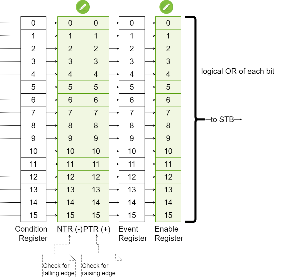
Positive Transition (PTR)
A positive transition is defined as the change of a bit from 0 to 1. If the positive transition filter is set and the according bit in the Condition Register changes from 0 to 1, the according bit in the Event Register is set.
The positive transition filter is useful when you want to get notified if an action has started (e.g. the measuring bit changes from 0 to 1 when a measurement starts).
By default, all positive transitions are enabled.
Negative Transition (NTR)
A negative transition is defined as the change of a bit from 1 to 0. If the negative transition filter is set and the according bit in the Condition Register changes from 1 to 0, the according bit in the Event Register is set.
The negative transition filter is useful when you want to get notified if an action is finished (e.g. the measuring bit changes from 1 to 0 when the measurement stops).
By default, all negative transitions are disabled.
Usage
So the summarize, if you want that the summary bit in the STB register is set, when a register value changes, you have to set two values:
- Either the bit in the positive or the negative transition filter, depending on which transition you are interested in.
- The bit in the
EnableRegister, so that the selected bit is forwared to the STB.
Questionable Register (QUES)
The Questionable Register set contains bits which give an indication of the quality of
various aspects of the signal. The Questionable Register is an Event Based Register as explained above. The values of the individual bits are listed below.
| Bit value | Code | Description |
|---|---|---|
| Bit 0 - 1 | VOLTage |
The quality of the voltage measurement can not be guaranteed. This bit is set when an overload was detected during measurement. |
| Bit 1 - 2 | CURRent |
This bit is not used. |
| Bit 2 - 4 | TIME |
This bit is not used. |
| Bit 3 - 8 | POWer |
This bit is not used. |
| Bit 4 - 16 | TEMPerature |
This bit is not used. |
| Bit 5 - 32 | FREQuency |
This bit is not used. |
| Bit 6 - 64 | PHASe |
This bit is not used. |
| Bit 7 - 128 | MODulation |
This bit is not used. |
| Bit 8 - 256 | CALIbration |
The quality of the calibration can not be guaranteed. This bit is set when the frequency range of an active full range calibration is not covering the frequency range of a performed measurement. |
| Bit 9 - 512 | Not used |
This bit is not used. |
| Bit 10 - 1024 | Not used |
This bit is not used. |
| Bit 11 - 2048 | Not used |
This bit is not used. |
| Bit 12 - 4096 | Not used |
This bit is not used. |
| Bit 13 - 8192 | INSTrument Summary |
A summary of the instruments register. |
| Bit 14 - 16384 | Command Warning |
This bit is not used. |
| Bit 15 - 32768 | Not used |
The usage of the most significant bit is not allowed since some controllers may have difficulty reading a 16 bit unsigned integer. |
The available commands to access the Questionable Register are:
:STATus:QUEStionable:CONDition?
:STATus:QUEStionable:NTRansition
:STATus:QUEStionable:PTRansition
Operation Register (OPER)
The Operation Register contains conditions which are part of the instrument's normal
operation. It is an Event Based Register as explained above. The values of the individual bits are listed below.
| Bit value | Code | Description |
|---|---|---|
| Bit 0 - 1 | CALIbrating |
The device is calibrating. |
| Bit 1 - 2 | SETTling |
This bit is not used. |
| Bit 2 - 4 | RANGing |
This bit is not used. |
| Bit 3 - 8 | SWEeping |
The device is performing a sweep. |
| Bit 4 - 16 | MEASuring |
The device is performing a measurement. |
| Bit 5 - 32 | Waiting for TRIGger Summary |
The device is waiting for a trigger signal. |
| Bit 6 - 64 | Waiting for ARM Summary |
This bit is not used. |
| Bit 7 - 128 | CORRecting |
This bit is not used. |
| Bit 8 - 256 | Not used |
This bit is not used. |
| Bit 9 - 512 | REQuesting device lock |
The device lock is requested (the internal calibration is currently running). |
| Bit 10 - 1024 | LOCKing device |
The device is locked (in use). |
| Bit 11 - 2048 | Not used |
This bit is not used. |
| Bit 12 - 4096 | Not used |
This bit is not used. |
| Bit 13 - 8192 | INSTrument Summary |
A summary of the instruments register. |
| Bit 14 - 16384 | PROGram Running |
This bit is not used. |
| Bit 15 - 32768 | Not used |
This bit is not used. |
The available commands to access the Operation Register are: